Showing posts with label grinder timer. Show all posts

Thursday, December 20, 2012

2-Layered PCB with a Laser? Nah, Toner Transfer

I tried using the laser to remove some spray paint, and... I declare it a dud. Two major factors stymied this process for me for the moment:
  1. I didn't have the right spray paint (matte black) nor the right environment (dry and warm) for the paint I did have. What I did get to stick to the copper had a very uneven surface.
  2. The laser is... finicky. I can't tell if the layers were wildly inconsistent, if the paint behaved differently as it dried, or if maybe the laser had trouble, not liking the cold temperature or moist environment. I never can tell if it's about to give up.
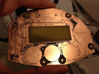
Impatient as usual, I used my regular method: laser printer toner transfer. Determined to make a 2-sided board work, I spent a while aligning corner crop marks and pre-taping the paper with the toner before laminating it to the copper. The toner transfer worked beautifully-- perfect result laminating it ten times (5 up, 5 down), but the top-bottom alignment, while close, may not be close enough. At this point it's etched (see photo) and drilled, but there are still bridges and the misalignment will make assembly an adventure.

Looking at guides online, (especially the tutorial at An Engineer's Life which so many people are linking to today,) it does seem like most people use a photographic process and abandon toner transfer when they go for double-sided and SMD. Before going that route, I want to take toner transfer further though-- I've had such good results so far, the only issue is top-bottom alignment. The biggest sources of alignment error:
  1. Top-bottom alignment of printed out patterns. A light box, some magnets, and tape should do the trick-- I need to see the registration targets better. Update: lightbox on the way from B&H.
  2. The laminator binds and jerks sometimes, which could distort the pattern slightly. It's hard to tell without sending through a test image, but it seems like time to take apart the laminator and see about modding it to separate the rollers a hair.
I'm happy with a slightly lower level of quality with toner transfer because it's a simpler process with fewer (and cheaper) expendables that can also transfer labeling to the top and bottom after etching.

Wednesday, April 11, 2012

New Workshop!

We moved recently, and one of the features that drew us to our new home was a sun room in the back, about 9'x15', full of light and perfect for a workshop!

One corner is ideal for the laser, with a dryer vent for routing its (filtered) fumes outside. With two rolling racks for storage and two desks, I hope we'll have room for a small heavy bench and drill press stand. Good thing the Printrbot is (er, will be) small, we have big plans for this (not so) little room.

Funny to look at my "Workshop!" post from two years ago, most of those projects haven't advanced much, but the grinder timer has gone through a few versions and the flight suit ended up being by far my most complicated project so far.

Thursday, November 3, 2011

Flight Suit Excursions, Grinder Timer V4

I've had a lot of fun with my Arduino-based projects lately! I got the flight suit working again for Decompression last month and had a blast dancing and hanging out in the crushing crowds. I wore it again last Saturday night for the work Halloween party and then again Monday night for 7 Walkers at the Great American Music Hall where Liz balanced out my high tech audio meter with her low tech VU meter-- analog and fully manual :)

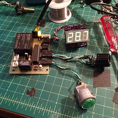
Next up is V4 of the coffee grinder timer, a one-off to replace the V2 timer we're using now. It's an all-in-one circuit board designed to fit in a Hammond 1455-series case. There's an AC-DC converter on the board to supply 5V, and breakouts on the left (in white) for power and on the right (black) for the display, light sensor, rotary encoder, and lit button. I may finish it without the light sensor since it's so close to being done and looks so much better (especially on the inside!) than what we're running now.

Thursday, June 16, 2011

3-Digit 7-Segment Display With an SAA1064


Working on the grinder timer project, I built out a basic circuit (EAGLE .sch) with an NXP SAA1064 and resurrected a test sketch (Arduino .pde) for it. The SAA1064 works beautifully for driving common anode 4-digit 7-segment displays with constant current per segment, from 3 to 21 mA in 3mA increments; in this case I'm only driving three digits since that's what the design calls for.

There are two buttons in the test sketch (on D10 and D11), the first to change count modes (seconds, tenths, hundredths, hex, and "chase") and the second to cycle through the seven current settings.

This schematic is identical to one I did a board layout for with an SO24 package chip, but for some reason those boards didn't work; maybe something in manufacture or assembly bridged pins somewhere. I'll redo the layout and see what happens, with vias further from pads.

Tuesday, September 7, 2010

Coffee Control

It looks like we'll have remote control of the grinder timer by the end of the week, along with power for Mr. Coffee and the Gaggia Classic!

The first step (mentioned in my previous post) was to get my old (V1.0) Adafruit Ethernet Shield up and running with an XPort Direct+ and the color picker sketch on the examples page. Then I stripped down the sketch, reconfiguring it for general pin control: toggle outputs, set PWM output values, pulse, and read analog values. After that, I simplified it for the coffee control project which only needs three digital output pins.

One obstacle was getting my LAN to the kitchen counter, and an old AirPort Extreme from my scrap bin (found on the street!) did the trick: it now wirelessly bridges our home network via WDS and connects to the ethernet shield with a cable, its USB port powering my minimal Arduino-compatible board underneath with enough 5V power to spare for Mr. Coffee's relay; I'll add a 12V source for a bigger, higher power relay to switch the Gaggia Classic.

The Arduino side of the system works great, serving a web form (at right) to turn the two power relays on or off and to trigger the grinder timer. The last part is always the hardest, though: wiring and casing it all up. Safe wiring will take some time to nail down, with Mr. Coffee needing ~1025W and the Gaggia Classic rated at 1370W (!). As for the case itself, lucky for me some folks from Ponoko are scheduled to make a presentation tomorrow (er, later today ;) at the Make:SF Meetup-- just the info I need, right when I need it!

Tuesday, August 17, 2010

Workshop!

After over a month of planning, boxing, and finally moving into a new home, I'm ready to get back to projects working in a dedicated workshop/office space!

Arduino-based projects, all within reach:
  • Mutetater: get it working for the Sharp TV I have, at least. This is more a challenge of IR encoding/decoding than anything else, so I'll reel back my code and try to re-approach the examples I've looked through before.
  • Resurrect Growduino for an herb garden on the upper desk, easy since there are power outlets available so I can sidestep solar power issues for now and get stuff growing.
  • Net-enabled coffee grinder timer so it can be controlled through a simple web interface, via an iPhone on the local network. I think it would mostly involve working with the ethernet shield, then maybe "shield-ifying" the grinder timer or building ethernet capability into the single-PCB circuit. Then I can start building out a control system for the Gaggia Classic.
  • Remote-controlled curtain system for the TV. Mostly involving IR decoding, simple (MOSFET) motor control, some limit switches, mounting hardware, and sewing.
  • PPAC: um, why aren't the relays firing?! Buttons work, so I need to disassemble it and check the output pins, then position the "pea" for exciting wake-up sequences.
  • Intervalometer ("intervalomejar"?): get a simple one working for timelapse using the FSM (Finite State Machine, not Flying Spaghetti Monster) library.
I'll add more later, just want to get a list going so I can start building some test sketches. Other tech to sketch for more complex projects:
  • PID for temperature and motor control
  • Temperature sensing for PID control: thermocouples

Tuesday, March 16, 2010

PPAC Fixes, Minimalduino, Timer

I've been busy lately and haven't had as much time as I'd like to tinker, but I've gotten things moving in the last two weeks and am overdue to post.

Hoping to show off the alarm clock a little, I brought the PPAC (including power block, valve tree, and tank) to the Make:SF Meetup last month, and while talking and hooking it up at the same time, plugged the AC supply into the DC power socket! The voltage regulator fizzled but the power board seems fine otherwise. Strangely, of all things, the LCD display was dead as well... though I may have killed it when disassembling the can..:o I ordered a better looking LCD replacement which I'll install in the next few days-- green-on-black instead of black-on-green: Newhaven NHD-0216K1Z-NSPG-FBW-L.

The minimalduino project is still moving forward: I'm using a test board I made at home a few weeks ago, populated with as little as possible: chip, caps, resonator, female headers, reset and male FTDI header. I'll move a few traces around but it's pretty much there, and hope to get three test boards made through the DorkbotPDX PCB order, deadline noon on March 29. I've built a spreadsheet with costs, and it seems like I could make a batch of 25 kits at just under $15 each. I'm not sure if it's worth the trouble though.

A few weeks ago, I built a new coffee grinder timer with a re-worked sketch and single board, then handed it off to fellow coffee fiend HF for ideas on how to make the ideal grinder timer. One thing we agreed on is that tenths of a second would be cool, so last night I had a great time working out a sketch to drive a common anode 3-digit 7-segment display using an SAA1064 IC. Of course having a sketch to start with made things straightforward-- thanks Alessandro Saporetti! I reworked the code to make it more general purpose, using all of the chip's functions including multiplexed (versus not) and changing the constant current output (7 output levels possible, from 3 to 21mA). [Video to come]